I created a branch from mbed master, which contains KL46Z GCC ARM support.
KL46Z is similar to KL25Z. Be aware of their differences. KL46Z is bigger brother of KL25Z, it has on top of KL25Z features - I2S and LCD module. The memory footprint is also bigger (256mb flash, 32kb ram).
I officially started testing today, I made GCC running with my makefile few days ago. This time I took a look at MUX options in HAL layer and interrupts. Of course, there were problems I had to face.
I added KEIL (in mbed is named ARM). I met again with BKTP instruction in KEIL (heap was set to 0, as the
last time), clock configuration was set to a wrong value. Consequently, timer's clock were not activated - no Ticker interrupt.
All this updates are currently on my branch, will be available soon.
September 29, 2013
September 28, 2013
TSS - Touch sensing (introduction)
There was a new TSS released in the beginning of this month, version 3.1. I'll describe the features I consider are important to highlight.
The capacitive measurement is active RESPONSE TIME-1 number of an execution of TSS_Task. This implies that a noise is measured always once until the decision is made about the electrode status (touch/release). Since the moment, the noise is detected, the noise mode is active until there's no noise on any electrode. Without any noise, TSS switches back to the capacitive measurement.
The example named TWRKXX_DEMO_EMC shows usage of AFID and the noise mode.
There are 5 controls (as in TSS), one system and the control factory. I don't introduce callback's classes here.
TSS_System is a singleton, which takes care of TSS settings. If you don't want to use any control, system handles everything and you can retrieve informations which are available (like electrode status).
If you want to use controls, take a look at TSS_ControlFactory which facilitates creation of new controls. Doesn't need to be used.
The entire API contain doxygen comments. Open FRDMKLXX_DEMO_CPP example which is located in EXAMPLES folder to see how to create new control and register callback.
If you have any questions, don't hesitate to ask in comments here or on freescale community.
What's new?
- supports TSI noise mode
- new patented AFID keydetector - connected with the noise mode - noise robust (capable of passing EN 61000-4-6)
- C++ wrapper
AFID + noise mode
The TSS noise mode is available only for Kinetis L. How does it work inside TSS?The capacitive measurement is active RESPONSE TIME-1 number of an execution of TSS_Task. This implies that a noise is measured always once until the decision is made about the electrode status (touch/release). Since the moment, the noise is detected, the noise mode is active until there's no noise on any electrode. Without any noise, TSS switches back to the capacitive measurement.
The example named TWRKXX_DEMO_EMC shows usage of AFID and the noise mode.
C++ wrapper
We added C++ wrapper for entire TSS which simplifies TSS usage. You still have to define system setup header file (that's how TSS was designed, I would like to change this). C++ supports all features which TSS provides.There are 5 controls (as in TSS), one system and the control factory. I don't introduce callback's classes here.
TSS_System is a singleton, which takes care of TSS settings. If you don't want to use any control, system handles everything and you can retrieve informations which are available (like electrode status).
If you want to use controls, take a look at TSS_ControlFactory which facilitates creation of new controls. Doesn't need to be used.
The entire API contain doxygen comments. Open FRDMKLXX_DEMO_CPP example which is located in EXAMPLES folder to see how to create new control and register callback.
If you have any questions, don't hesitate to ask in comments here or on freescale community.
September 26, 2013
freedom KL46Z on mbed (update)
Perhaps you missed this, KL46Z was merged to mbed. A user Mike ported KL46Z which currently supports only ARM GCC. He was using a makefile and startup files which were written for KL25Z, I am feeling rewarded that it helped to port another platfrom!
I tested my GPIO mbed application which I shared for freedom KL25Z ARM GCC, with same makefile (not much changed). I was able to run it, debug it. I am going to add ARM compiler support and review the code.
Stay tuned, more freedom platforms are cominG!
I tested my GPIO mbed application which I shared for freedom KL25Z ARM GCC, with same makefile (not much changed). I was able to run it, debug it. I am going to add ARM compiler support and review the code.
Stay tuned, more freedom platforms are cominG!
September 20, 2013
mbed and cc3000 (wifi)
I share with you that we are currently working on new cc3000 driver directly aimed to be used with mbed and libraries shared there.
There are already at least 2 repositories which contain a host driver ported to mbed (written in C, mainly). Thus I began to write a new C++ interface, with a goal to be easier to use for mbed community. The host driver was ported a while ago, tested with 2 examples which were tested at least on 2 mbed platforms (I am using KL25Z - Wi-Go board). I decided to write more applications , while searching, I discovered the mbed socket interface. This is a priority at the moment, will enable users to use many libraries which are written using that interface.
I am not able to anticipate the release date at the moment. There's a lot of work still to do. Anybody out there interested ?
Want to join the development? Find me on mbed.org, send me a direct message there with your email. I'll share more details if requested.
September 13, 2013
mbed GCC with eclipse KL25Z (Part 2)
This is finally the debugging part which I described in one of my comments. There are at least 3 options to debug KL25Z with GCC:
CMSIS-DAP with openOCD, external Jlink or openSDA Jlink firmware.
CMSIS-DAP is still in a development, according to the site cmsis-dap: add initial cmsis-dap support [openocd.zylin.com]. Thus I went straight to Jlink's options. The last option is the most useful for many users. I will describe to process how to set it and be able to debug your KL25Z with no external parts needed.
1. step - download Jlink firmware
Visit a webpage SEGGER openSDA Jlink [http://www.segger.com], there are links on the bottom of the webpage. Be aware of some limitations which are stated there.
Download OpenSDA Jlink firmware http://www.segger.com/admin/uploads/userfiles/file/J-Link/JLink_OpenSDA.zip
2. step - get serial number of openSDA
Switch your KL25Z to the bootloader mode (unconnect usb, hold reset button, plug it back in while holding button, release button). Copy there unzipped file JLink_OpenSDA.sda
Restart the board, then plug it back to your PC.
In case you don't have installed jlink software (gdb, jlink console). Get this program from here which will display the serial number of your openSDA jlink in order to download the jlink software (you need jlink's serial number which we obviously don't know as we don't have external tool).
3. step - install JLink software
Download Jlink firmware here JLink software [http://www.segger.com]
This will install Jlink configurator, check serial number, type it in the page pasted above and download jlink software.

After installing jlink software, navigate to a jlink's folder in my case c:\Program Files\Segger\JLinkARM_V472a, open JLink.exe program. It will display this warning, check the below button, it won't display today, and press accept.
 This should be an output if your board is connected and the jlink driver was installed properly:
 Jlink is connected, we proceed to the eclipse project we created in part 1.
4. step - run jlink gdb server
The program is located again in the Segger Jlink software folder, named JLinkGDBServer. Execute the program, it pops the config window, set it as it is shown on the picture:
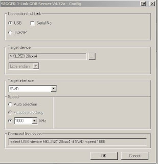 Press OK and it should display the following lines
 As you see, it's connected to my freedom board. Keep it running, we will connect to it once we complete debug settings in Eclipse.
5. step - set eclipse project
Before going further, your eclipse must have installed GDB Hardware Debugging plugin. If not, please find a tutorial how to install that plugin.
Open your mbed KL25Z project, select your project, click on the green bug (the top right corner on the picture) and select Debug configuration.
 Click with your right mouse button on GDB Hardware Debugging, create New one
 On the bottom of the window it is "Using GDB (DSF) Hardware .... Select other . Click on select other and we need to check button Use configuration specific and select Standard GDB Hardware
 Now we are back in Debug configurations, select Debugger tab and fill details according to the picture below
 The tab Startup needs this details
The first input window (Initialization Commands) contain on my side the following commands
target remote localhost:2331
monitor clrbp
monitor endian little
monitor speed 1000
monitor reset
monitor sleep 100
monitor speed auto
The last input window (Run Commands) (Note: I prefer to put a breakpoint in Reset_Handler)
break main
continue
 I assume your jlink gdb server is running, click on the debug icon on the bottom of Debug configurations window.
This should be your window (breakpoint is set in main, thus it stops there).

Now led should be blinking.
The debugging part over ! There are tutorials how to work with gdb. If anything not correct, please use comments below or contact me on mbed. I'll add this to my notepad there.
CMSIS-DAP with openOCD, external Jlink or openSDA Jlink firmware.
CMSIS-DAP is still in a development, according to the site cmsis-dap: add initial cmsis-dap support [openocd.zylin.com]. Thus I went straight to Jlink's options. The last option is the most useful for many users. I will describe to process how to set it and be able to debug your KL25Z with no external parts needed.
1. step - download Jlink firmware
Visit a webpage SEGGER openSDA Jlink [http://www.segger.com], there are links on the bottom of the webpage. Be aware of some limitations which are stated there.
Download OpenSDA Jlink firmware http://www.segger.com/admin/uploads/userfiles/file/J-Link/JLink_OpenSDA.zip
2. step - get serial number of openSDA
Switch your KL25Z to the bootloader mode (unconnect usb, hold reset button, plug it back in while holding button, release button). Copy there unzipped file JLink_OpenSDA.sda
Restart the board, then plug it back to your PC.
In case you don't have installed jlink software (gdb, jlink console). Get this program from here which will display the serial number of your openSDA jlink in order to download the jlink software (you need jlink's serial number which we obviously don't know as we don't have external tool).
3. step - install JLink software
Download Jlink firmware here JLink software [http://www.segger.com]
This will install Jlink configurator, check serial number, type it in the page pasted above and download jlink software.

After installing jlink software, navigate to a jlink's folder in my case c:\Program Files\Segger\JLinkARM_V472a, open JLink.exe program. It will display this warning, check the below button, it won't display today, and press accept.


4. step - run jlink gdb server
The program is located again in the Segger Jlink software folder, named JLinkGDBServer. Execute the program, it pops the config window, set it as it is shown on the picture:


5. step - set eclipse project
Before going further, your eclipse must have installed GDB Hardware Debugging plugin. If not, please find a tutorial how to install that plugin.
Open your mbed KL25Z project, select your project, click on the green bug (the top right corner on the picture) and select Debug configuration.


The first input window (Initialization Commands) contain on my side the following commands
target remote localhost:2331
monitor clrbp
monitor endian little
monitor speed 1000
monitor reset
monitor sleep 100
monitor speed auto
The last input window (Run Commands) (Note: I prefer to put a breakpoint in Reset_Handler)
break main
continue

This should be your window (breakpoint is set in main, thus it stops there).

Now led should be blinking.
The debugging part over ! There are tutorials how to work with gdb. If anything not correct, please use comments below or contact me on mbed. I'll add this to my notepad there.
September 12, 2013
How to flash/debug KL05 with mbed library offline in KEIL (tutorial)
Hello,
I finally allocated one evening to finish what I should have done earlier. I did not anticipate that at this time KL05 wouldn't be online on mbed (no mbed interface for this board yet). This is step guide how to debug it with free version of KEIL (I'll add ARM GCC later).
1. step - clone mbed git repository from github
mbed git repository is here mbed git repository [github.com]
If you don't use git, or github, download repository as zip file. This is crucial for offline debugging.
Create a new file named private_settings.py in mbed/workspace_tools. Put the following source code there (I am using KEIL 4.6 at the moment, KEIL seldomly changes their folder structure).
Time to build our own mbed library, type on your command line python build.py -m KL05Z -t ARM from workspace_tool directory.
If everything went ok, the output should state Build successes: * ARM::KL05Z. Built library is now inside build folder (same level than workspace_tools and libraries folders).
2. step - create KEIL project
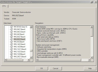
Create new folder (I name mine KL05_demo) and copy there entire folder mbed which is inside build directory. Open KEIL, select Project on the top toolbar and create a new project inside our new created directory. It asks you to choose a processor, MKL05Z32xxx4 is assembled on the freedom KL05Z.
Click OK, it ask if you want to copy startup file, click No. We don't need it. This should be an output inside the Project window

Remove that Source Group 1.
3. step - main code file
Create new main.cpp inside the project directory and paste there the simple demo. Here's my code:
4. step - Set our new created project for KL05Z
The tab which we start with, it's User. Add there fromelf --bin -o test05_KL05Z.bin test05.axf
This step can be skipped because KL05Z does not have the mbed interface yet. Once it does, this command creates a .bin file which you can copy to a mbed drive.

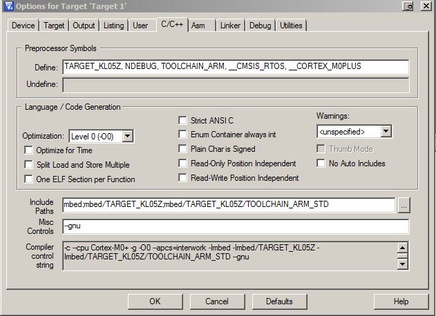
5.step - C/C++ tab
Fill Define with
TARGET_KL05Z, NDEBUG, TOOLCHAIN_ARM, __CMSIS_RTOS, __CORTEX_M0PLUS
The include paths should contain folders (add folder with the first icon, a small rectangle):
mbed
mbed/TARGET_KL05Z
mbed/TARGET_KL05Z/TOOLCHAIN_ARM_STD

The misc Controls should contain --gnu command.

The asm tab should also have filled same Include Paths as C/C++. Copy them there.
6. step - Linker tab
Uncheck Memory Layout from Target Dialog. We need to add scatter file which is located inside mbed/TARGET_KL05/TOOLCHAIN_ARM_STD, named MKL05Z4.sct. Add it there.
This is what it should display : .\mbed\TARGET_KL05Z\TOOLCHAIN_ARM_STD\MKL05Z4.sct
Add precompiled mbed files to Misc controls which is right below Scatter file:
mbed/TARGET_KL05Z/TOOLCHAIN_ARM_STD/sys.o
mbed/TARGET_KL05Z/TOOLCHAIN_ARM_STD/retarget.o
mbed/TARGET_KL05Z/TOOLCHAIN_ARM_STD/cmsis_nvic.o
mbed/TARGET_KL05Z/TOOLCHAIN_ARM_STD/system_MKL05Z4.o
mbed/TARGET_KL05Z/TOOLCHAIN_ARM_STD/startup_MKL05Z4.o
mbed/TARGET_KL05Z/TOOLCHAIN_ARM_STD/mbed.ar
7. step - Debug tab
Now select the right radio button Use and select from drop-down menu CMSIS-DAP
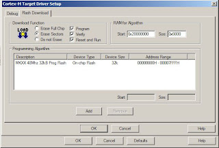
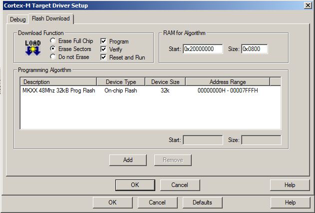
8. step - Utilities
Same applies for Use Target Driver for Flash Programming - CMSIS-DAP. Click on Settings and verify everything is set according to target.
10. step - adding sources
Create new group (I name it sources) and click with your right mouse button on the group and select Add files to group .... Here's my workspace.

Now it is finally time to compile, if you followed my steps, you should get no errors ! The picture below shows window after reflashing my KL05Z, part starting with a line LOAD "C...." it's a flashing part.

We can't proceed with a bin file, due to a lack of mbed interface for our board. But CMSIS-DAP allows us to flash/debug it. Before we proceed to a debugging part, if your KL05 has not been flashed with CMSIS-DAP firmware, download it from freescale webpage - FRDM-KL05Z_QSP.zip (quick start package). There's CMSIS-DAP_OpenSDA.S19 file inside OpenSDA Applications folder. I set my board to bootloader mode and flash it with this file. Reconnect your board, and let's flash it.
Build (F7) and download your code (LOAD icon on top). This flashes KL05Z and LED should be blinking. If you want to debug it , press Ctrl+F5 (or top selection Debug -> Start/stop debuging session). Happy flashing your KL05!
If anything not clear, leave a comment.
I finally allocated one evening to finish what I should have done earlier. I did not anticipate that at this time KL05 wouldn't be online on mbed (no mbed interface for this board yet). This is step guide how to debug it with free version of KEIL (I'll add ARM GCC later).
1. step - clone mbed git repository from github
mbed git repository is here mbed git repository [github.com]
If you don't use git, or github, download repository as zip file. This is crucial for offline debugging.
Create a new file named private_settings.py in mbed/workspace_tools. Put the following source code there (I am using KEIL 4.6 at the moment, KEIL seldomly changes their folder structure).
from os.path import join

ARM_PATH = "C:/Program Files/Keil/TAD/ARM"
ARM_BIN = join(ARM_PATH,"ARMCC","bin")
ARM_INC = join(ARM_PATH,"RV31","INC")
ARM_LIB    = join(ARM_PATH,"ARMCC","lib")
ARM_CPPLIB = join(ARM_PATH, "ARMCC","lib","cpplib")

BUILD_OPTIONS = ["debug-info"]
Time to build our own mbed library, type on your command line python build.py -m KL05Z -t ARM from workspace_tool directory.
If everything went ok, the output should state Build successes: * ARM::KL05Z. Built library is now inside build folder (same level than workspace_tools and libraries folders).
2. step - create KEIL project
Create new folder (I name mine KL05_demo) and copy there entire folder mbed which is inside build directory. Open KEIL, select Project on the top toolbar and create a new project inside our new created directory. It asks you to choose a processor, MKL05Z32xxx4 is assembled on the freedom KL05Z.

Click OK, it ask if you want to copy startup file, click No. We don't need it. This should be an output inside the Project window
Remove that Source Group 1.
3. step - main code file
Create new main.cpp inside the project directory and paste there the simple demo. Here's my code:
#include "mbed.h"

DigitalOut myled(LED1);

int main() {
    while(1) {
        myled = 1;
        wait(0.2);
        myled = 0;
        wait(0.2);
    }
}
4. step - Set our new created project for KL05Z
The tab which we start with, it's User. Add there fromelf --bin -o test05_KL05Z.bin test05.axf
This step can be skipped because KL05Z does not have the mbed interface yet. Once it does, this command creates a .bin file which you can copy to a mbed drive.

5.step - C/C++ tab
Fill Define with
TARGET_KL05Z, NDEBUG, TOOLCHAIN_ARM, __CMSIS_RTOS, __CORTEX_M0PLUS
The include paths should contain folders (add folder with the first icon, a small rectangle):
mbed
mbed/TARGET_KL05Z
mbed/TARGET_KL05Z/TOOLCHAIN_ARM_STD

The misc Controls should contain --gnu command.
The asm tab should also have filled same Include Paths as C/C++. Copy them there.
6. step - Linker tab
Uncheck Memory Layout from Target Dialog. We need to add scatter file which is located inside mbed/TARGET_KL05/TOOLCHAIN_ARM_STD, named MKL05Z4.sct. Add it there.
This is what it should display : .\mbed\TARGET_KL05Z\TOOLCHAIN_ARM_STD\MKL05Z4.sct
Add precompiled mbed files to Misc controls which is right below Scatter file:
mbed/TARGET_KL05Z/TOOLCHAIN_ARM_STD/sys.o
mbed/TARGET_KL05Z/TOOLCHAIN_ARM_STD/retarget.o
mbed/TARGET_KL05Z/TOOLCHAIN_ARM_STD/cmsis_nvic.o
mbed/TARGET_KL05Z/TOOLCHAIN_ARM_STD/system_MKL05Z4.o
mbed/TARGET_KL05Z/TOOLCHAIN_ARM_STD/startup_MKL05Z4.o
mbed/TARGET_KL05Z/TOOLCHAIN_ARM_STD/mbed.ar
7. step - Debug tab
Now select the right radio button Use and select from drop-down menu CMSIS-DAP
8. step - Utilities
Same applies for Use Target Driver for Flash Programming - CMSIS-DAP. Click on Settings and verify everything is set according to target.
10. step - adding sources
Create new group (I name it sources) and click with your right mouse button on the group and select Add files to group .... Here's my workspace.

Now it is finally time to compile, if you followed my steps, you should get no errors ! The picture below shows window after reflashing my KL05Z, part starting with a line LOAD "C...." it's a flashing part.

We can't proceed with a bin file, due to a lack of mbed interface for our board. But CMSIS-DAP allows us to flash/debug it. Before we proceed to a debugging part, if your KL05 has not been flashed with CMSIS-DAP firmware, download it from freescale webpage - FRDM-KL05Z_QSP.zip (quick start package). There's CMSIS-DAP_OpenSDA.S19 file inside OpenSDA Applications folder. I set my board to bootloader mode and flash it with this file. Reconnect your board, and let's flash it.
Build (F7) and download your code (LOAD icon on top). This flashes KL05Z and LED should be blinking. If you want to debug it , press Ctrl+F5 (or top selection Debug -> Start/stop debuging session). Happy flashing your KL05!
If anything not clear, leave a comment.
September 11, 2013
freedom boards (K20, KL46) arrived !
I have received 2 new freedom boards (K20 and KL46, they have been on
the market, but I have not had them yet).. I am fully equipped here
(all hardware almost ready, only to solder sockets).
First to come it's still KL02, it has been on hold since July. Sorry guys.

First to come it's still KL02, it has been on hold since July. Sorry guys.
Subscribe to:
Posts (Atom)