Showing posts with label tutorial. Show all posts

January 11, 2014

CoIDE with KL25Z and mbed (C++) (tutorial)

I decided to start contributed to open source one year ago, as my start project I selected CoX library. I was pleased with CooCox CoIDE back in those days, it's light, easy to set-up, fast and was reliable. However, I abandoned CoX library since than as well as their IDE named CoIDE. This tutorial brings back CoIDE to my life as GCC is supported to all available Freescale targets.

I am running this tutorial on KL25Z, but as I checked, also NXP chips are supported there so this should be applied to more mbed targets than just KL25Z.

I ported CMSIS-DAP to many new freescale chips, now also bootloader is available. I was looking for open source IDE with working debugger. Finally, found something which is fast, reliable, and works with just few steps.

The very first thing is to install CoIDE.  Visit link CooCox IDE [www.coocox.org] . The installation is straightforward. Once installed, open your CoIDE and select toolchain path


I added there the following path :
C:\Program Files\GNU Tools ARM Embedded\4.7 2013q3\bin

If you want to test mbed with KL25Z in CoIDE, download the project here Hello world project KL25Z CoIDE [mbed.org/media/uploads/Kojto]. I'll explain below how to create your own project, so you can change anything you like like adding your own sources, libraries.

In the same tab as Select Toolchain Path, there's New Project (the top selection). Create a new project, select a name and click next. I use KL25Z_mbed as name of the project (which will be used in some steps, so might follow the same).
The next step is to select a chip or a board, just use Chip
The chip which is assembled on the freedom KL25Z board, is MKL25Z128VLK4. Then click Finish. The project is created and should be visible in the right bottom corner.

This creates an empty project with one code file (main.c). Please remove that file. Export a basic hello world example from the mbed site (GCC export option), as reference this one Hello world example [mbed.org/users/simon/code]. Add it to your online compiler and export it to GCC.

Unzip the exported Hello world anywhere. The example has only main.cpp file and the mbed folder which contains mbed library with header files + some object files. We need to copy those files to our new created project's folder. There is already .coproj file which gets created later, so don't get surprised by the below picture.

 After copying them, we go back to CoIDE where we need to set-up our new project. Click on the project with the right-button on your mouse, and select Configuration.
This is the crucial step, to set up correctly gcc project. There are few tabs : Device, Compile, Link and more.

We can skip device, as we already set device (chip). Go to the Compile tab:

Add include paths (mbed folder, target_kl25z folder inside and the toolchain_gcc_arm which is inside target_kl25z folder). Add to Misc. Controls:

-fno-common; -fmessage-length=0; -Wall; -fno-exceptions; -ffunction-sections; -fdata-sections; -DTARGET_KL25Z; -DTARGET_M0P; -DTARGET_Freescale; -DTOOLCHAIN_GCC_ARM; -DTOOLCHAIN_GCC; -D__CORTEX_M0PLUS; -DARM_MATH_CM0PLUS;  -std=gnu++98

We could add those defines up there to Defined Symbols, does not matter though. This should be for compile tab, move to the Link tab.
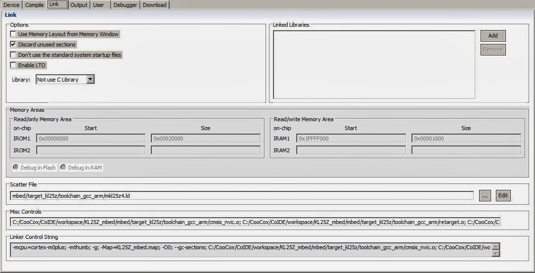

The important detail here is to uncheck Use Memory Layout from Memory Window and add linker script path (scatter file).

Add this to Misc. Controls:
--specs=nano.specs; ${project.path}/mbed/target_kl25z/toolchain_gcc_arm/cmsis_nvic.o; ${project.path}/mbed/target_kl25z/toolchain_gcc_arm/retarget.o; ${project.path}/mbed/target_kl25z/toolchain_gcc_arm/startup_MKL25Z4.o; ${project.path}/mbed/target_kl25z/toolchain_gcc_arm/system_MKL25Z4.o;

Add to Linked Libraries (just type the names there):
mbed, stdc++ , supc++ , m , gcc , c , nosys

The last thing to check is Debug tab, where select CMSIS-DAP, SWD and 1MHZ (this should be set as default for that chip).

Now press F7 (BUILD) which builds the project. It should display BUILD SUCCESSFUL if everything is correct along with size of the each areas and the command invoked.

Connect your board which mbed interface (CMSIS-DAP) and click on Debug icon (or press CTRL+F5). Debugging starts, it puts the breakpoint inside the main function, as it's shown in the picture below.


Happy debugging ! I am surprised with a speed, compared to pyOCD I tried with eclipse, this is really quick.

I will find out when other mbed chips are going to be supported.

Update1: I am currently working on an exporter to CoIDE for KL25Z, and probably later also other targets will follow.


December 29, 2013

How to build mbed src and Hello world (AMRCC, ARM GCC) (tutorial)

This tutorial is dedicated to building mbed sources and exporting hello world. K20D5M is going to be used as an example, because it is still not available in the mbed online compiler. Thus this give us to compile any application based on mbed libraries. My machine is running Windows so paths presented in the 2nd step are for windows.

1. Download the mbed github repository

If you are familiar with git, just clone repository using git clone command. For those who don't use git, download the repository as archive (zip).
Link mbed src ZIP archive (~5MB) [github.com/mbedmicro/mbed]

After downloading is completed, unzip the archive.

2. Set your toolchain paths

There few toolchains which can be used, I'll present ARM GCC and ARMCC (uVision). Create a new file named private_settings.py in the workspace_tools directory. This private settings file defines settings which overrides default settings.

from os.path import join
#KEIL
ARM_PATH = "C:/Keil/ARM"
ARM_BIN = join(ARM_PATH,"ARMCC","bin")
ARM_INC = join(ARM_PATH,"RV31","INC")
ARM_LIB    = join(ARM_PATH,"ARMCC","lib")
ARM_CPPLIB = join(ARM_PATH, "ARMCC","lib","cpplib")

#GCC ARM
GCC_ARM_PATH = "C:/Program Files/GNU Tools ARM Embedded/4.7 2013q3/bin"

BUILD_OPTIONS = ["debug-info"]

ARM_ paths are used for ARMCC (uVision IDE, paths for each folders might vary, as I had problems with previous versions, because they changed the folder structure), GCC_ARM_ path for ARM GCC toolchain path. Set those according your installation folder.
I use debug-info build-option, to include debug symbols.

3. Build sources for your target

To build mbed sources for TARGET and TOOLCHAIN, use command:
python build.py -m TARGET -t TOOLCHAIN

The list of supported targets is quite long, to check if your TARGET is supported TARGETS array [github.com/mbedmicro/mbed].
Each TARGET defines supported TOOLCHAIN. For example, K20D5M has ARM and GCC_ARM.

To build for ARM (that's ARMCC used in uVision for example)
python build.py -m K20D5M -t ARM

To build for GCC ARM
python build.py -m K20D5M -t GCC_ARM

If you just invoke command without -t, the target will be built for all supported toolchains.

4. Using exporters

As soon as you have built mbed sources for your target, go to my previous tutorial about using exporters. There is just shown to export Hello world example.

How to use mbed exporters

5. Build an application

Using ARM GCC, use makefile to build an application. If uVision is used, build the application in the uVision IDE. No matter what toolchain you use, they should generate a binary file, which can be copied to mbed msd drive. Same procedure as it's used by the mbed online compiler.

December 26, 2013

How to use mbed exporters (tutorial)

I always created my own projects while I was developing offline with mbed. Fortunately, there are exporters which I assume are used in the online compiler. They are available in the mbed sources, in the folder /workspace_tools/export, Github mbed - export folder [github.com/mbedmicro/mbed]

These exporters support more platforms than online compiler, thus if you see a platform in the mbed sources but is not yet available online, this is your chance to start using your target. It requires IDE or at least a toolchain to compile it.

What targets are currently supported by exporters?
  • NUCLEO_F103RB
  • KL25Z,
  • LPC1347
  • LPC11U24_301
  • LPC4330_M4
  • nRF51822,
  • LPC11U35_401
  • LPC810
  • KL46Z
  • LPC812
  • KL05Z
  • LPC1768
  • K20D5M
  • LPC4088
  • LPC11C24
  • MBED_MCU
  • LPC1114
  • LPC11U24,
  • STM32F407
  • LPC2368

To see what options are available, invoke project.py, an output:

d:\Code\git_repo\github\mbed\workspace_tools>python project.py


[ERROR] You have to specify one of the following tests:
[ 0] MBED_A1: Basic
[ 1] MBED_A2: semihost file system
[ 2] MBED_A3: C++ STL
[ 3] MBED_A4: I2C TMP102
[ 4] MBED_A5: DigitalIn DigitalOut
[ 5] MBED_A6: DigitalInOut
[ 6] MBED_A7: InterruptIn
[ 7] MBED_A8: Analog
[ 8] MBED_A9: Serial Echo at 115200
[ 9] MBED_A10: PortOut PortIn
[ 10] MBED_A11: PortInOut
[ 11] MBED_A12: SD File System
[ 12] MBED_A13: I2C MMA7660
[ 13] MBED_A14: I2C Master
[ 14] MBED_A15: I2C Slave
[ 15] MBED_A16: SPI Master
[ 16] MBED_A17: SPI Slave
[ 17] MBED_A18: Interrupt vector relocation
[ 18] MBED_A19: I2C EEPROM read/write test
[ 19] MBED_A20: I2C master/slave test
[ 20] MBED_A21: Call function before main (mbed_main)
[ 21] MBED_A22: SPIFI for LPC4088 (test 1)
[ 22] MBED_A23: SPIFI for LPC4088 (test 2)
[ 23] MBED_A24: Serial echo with RTS/CTS flow control
[ 24] BENCHMARK_1: Size (c environment)
[ 25] BENCHMARK_2: Size (float math)
[ 26] BENCHMARK_3: Size (printf)
[ 27] BENCHMARK_4: Size (mbed libs)
[ 28] BENCHMARK_5: Size (all)
[ 29] MBED_1: I2C SRF08
[ 30] MBED_2: stdio
[ 31] MBED_3: PortOut
[ 32] MBED_4: Sleep
[ 33] MBED_5: PWM
[ 34] MBED_6: SW Reset
[ 35] MBED_7: stdio benchmark
[ 36] MBED_8: SPI
[ 37] MBED_9: Sleep Timeout
[ 38] MBED_10: Hello World
[ 39] MBED_11: Ticker
[ 40] MBED_12: C++
[ 41] MBED_13: Heap & Stack
[ 42] MBED_14: Serial Interrupt
[ 43] MBED_15: RPC
[ 44] MBED_16: RTC
[ 45] MBED_17: Serial Interrupt 2
[ 46] MBED_18: Local FS Directory
[ 47] MBED_19: SD FS Directory
[ 48] MBED_20: InterruptIn 2
[ 49] MBED_21: freopen Stream
[ 50] MBED_22: Semihost
[ 51] MBED_23: Ticker 2
[ 52] MBED_24: Timeout
[ 53] MBED_25: Time us
[ 54] MBED_26: Integer constant division
[ 55] MBED_27: SPI ADXL345
[ 56] MBED_28: Interrupt chaining (InterruptManager)
[ 57] MBED_29: CAN network test
[ 58] MBED_30: CAN network test using interrupts
[ 59] MBED_31: PWM LED test
[ 60] CMSIS_RTOS_1: Basic
[ 61] CMSIS_RTOS_2: Mutex
[ 62] CMSIS_RTOS_3: Semaphore
[ 63] CMSIS_RTOS_4: Signals
[ 64] CMSIS_RTOS_5: Queue
[ 65] CMSIS_RTOS_6: Mail
[ 66] CMSIS_RTOS_7: Timer
[ 67] CMSIS_RTOS_8: ISR
[ 68] RTOS_1: Basic
[ 69] RTOS_2: Mutex
[ 70] RTOS_3: Semaphore
[ 71] RTOS_4: Signals
[ 72] RTOS_5: Queue
[ 73] RTOS_6: Mail
[ 74] RTOS_7: Timer
[ 75] RTOS_8: ISR
[ 76] RTOS_9: File
[ 77] NET_1: TCP client hello world
[ 78] NET_2: UDP client hello world
[ 79] NET_3: TCP echo server
[ 80] NET_4: TCP echo client
[ 81] NET_5: UDP echo server
[ 82] NET_6: UDP echo client
[ 83] NET_7: HTTP client
[ 84] NET_8: NTP client
[ 85] NET_9: Multicast Send
[ 86] NET_10: Multicast Receive
[ 87] NET_11: Broadcast Send
[ 88] NET_12: Broadcast Receive
[ 89] NET_13: TCP client echo loop
[ 90] UB_1: u-blox USB modem: HTTP client
[ 91] UB_2: u-blox USB modem: SMS test
[ 92] USB_1: Mouse
[ 93] USB_2: Keyboard
[ 94] USB_3: Mouse_Keyboard
[ 95] USB_4: Serial Port
[ 96] USB_5: Generic HID
[ 97] USB_6: MIDI
[ 98] USB_7: AUDIO
[ 99] CMSIS_DSP_1: FIR
[100] DSP_1: FIR
[101] KL25Z_1: LPTMR
[102] KL25Z_2: PIT
[103] KL25Z_3: TSI Touch Sensor
[104] KL25Z_4: RTC
[105] KL25Z_5: MMA8451Q accelerometer
[106] EXAMPLE_1: /dev/null
[107] EXAMPLE_2: FS + RTOS


Usage: project.py [options]

Options:
-h, --help show this help message and exit
-m MCU, --mcu=MCU generate project for the given MCU (NUCLEO_F103RB, KL25Z,
LPC1347, LPC11U24_301, LPC4330_M4, nRF51822,
LPC11U35_401, LPC810, KL46Z, LPC812, KL05Z, LPC1768,
K20D5M, LPC4088, LPC11C24, MBED_MCU, LPC1114, LPC11U24,
STM32F407, LPC2368)
-p PROGRAM The index of the desired test program: [0-107]
-i IDE The target IDE: ['ds5_5', 'gcc_arm', 'codered',
'codesourcery', 'uvision', 'iar']
-b Use the mbed library build, instead of the sources

The output provides all information which we need to build a project. As I pushed today K20D5M target to mbed repository, I'll take that as an example how to start with mbed target which is not yet supported in the mbed compiler.
If you don't have prebuilt mbed sources for your target, don't use -b option (you can use it if you have built your target previously, then it creates the mbed library, same output as from the online compiler exporter). If you have not built target sources, use -b option, error is shown.

The very first application we can build is Hello world ([ 38] MBED_10: Hello World) To build it for GCC ARM, invoke:

python project.py -m K20D5M -p 38 -i gcc_arm

If you receive an error which contains jinja2, that means the projects generators require jinja2 package, please add it to your python installation. Easy install can help you, for more help, a procedure Jinja2 windows - how to install [forums.udacity.com/questions]

The output should be many compiled files, at the end [OK]. In the mbed root directory, there's should be a new folder build. Inside in the path build/export/workspace are sources which were copied there by an exporter. In the build/export folder, should be located an archive MBED_10_GCC_ARM_K20D5M.zip
This archive contains the exported application, unzip it , invoke make command to build Hello world application.

December 19, 2013

debugging pyOCD gdb (tutorial)

I finally found a root cause of pyOCD locking kinetis chip. It took me quite a while to get into gdb server implementation, still many functions are unveiled for me. I am going to give you few tips what I would do once something is not working, or even to be sure that the right binary is going to be flashed. That's was my case, when I knew that pyOCD is flashing wrong data to the wrong address.

To start with, please if you use gdb server, change logging to DEBUG. This information is in gdb_test.py file.

logging.basicConfig(level=logging.DEBUG)

What helped me a lot to just see how data are interpreted, disable erasing the chip and then flashing as well. The code below is from gdbserver.py file. Don't forget, if you change anything inside pyOCD, please rerun setup.py file with a command

python setup.py install

Comment out two lines that init() and eraseALL().
if ops == 'FlashErase':
    self.flash.init()
    self.flash.eraseAll()
    return self.createRSPPacket("OK")

Flashing is carried out by calling programPage. Once you comment that line out, your target won't be flashed, so you can add a breakpoint anywhere there, write data to a file and see how they are interpreted.
while len(self.flashData) > 0:
    size_to_write = min(self.flash.page_size, len(self.flashData))
    #if 0 is returned from programPage, security check failed
    if (self.flash.programPage(flashPtr, self.flashData[:size_to_write]) == 0):
        logging.error("Protection bits error, flashing has stopped")
        return None
    flashPtr += size_to_write

    self.flashData = self.flashData[size_to_write:]

    # print progress bar
    sys.stdout.write('\r')
    i = int((float(flashPtr)/float(bytes_to_be_written))*20.0)
    # the exact output you're looking for:
    sys.stdout.write("[%-20s] %d%%" % ('='*i, 5*i))
    sys.stdout.flush()

There are many debug files commented in the implementation, which are intended for debugging purposes. The one below is from FlashDone command case, once you enable it, the bad_bin contains entire data which are going to be written to the flash. You can compare it to your bin generated, reveal if it matches the data.

elif 'FlashDone' in ops :
    flashPtr = 0
    bytes_to_be_written = len(self.flashData)

    """
    bin = open(os.path.join(parentdir, 'res', 'bad_bin.txt'), "w+")
    
    i = 0
    while (i < bytes_to_be_written):
        bin.write(str(self.flashData[i:i+16]) + "\n")
        i += 16
    """

How did I solve that problem with locking the chip? The most important addition is the security bits check, which is crucial. If data at the address 0x400 are not set to 0xFF, flashing should be stopped. If it would not be stopped, the chip can get secured, depending on the 16 byte value at that address.
I added the following lines, this is why debug logging is good to have enabled, you can see how those bits are set and are going to be flashed. This would have unveiled that chip is going to get locked.

def checkSecurityBits(self, address, data):
    #error if security bits have unexpected values
    if (address == 0x400):
        for i in range(12):
            logging.debug("data[%d] at add 0x%X: 0x%X", i, i, data[i])
            if (data[i] != 0xff):
                return 0

        logging.debug("data[%d] at add 0x%X: 0x%X", i+3, i+3, data[i+3])
        logging.debug("data[%d] at add 0x%X: 0x%X", i+4, i+4, data[i+4])
        if ((data[i+3] != 0xff) or (data[i+4] != 0xff)):
            return 0

    return 1

I even locked sometimes the chip (only security bit or some other bits, not mass erase bit). If chip is locked, mbed msd drive does not need to appear! Don't get frustrated. Follow the lines below, and you might get mbed drive again.
To solve this problem, get into bootloader mode (to disable CMSIS-DAP which enables another interface to access the mcu chip), use external jlink or just openSDA jlink. Execute the commands I shared in the previos post:
unlocking kinetis chip with jlink console [http://embeddedworldweb.blogspot.com]
Don't be afraid if it returns error, sometimes it does but chip is functional again. Just reconnect your board, mbed drive should appear again if the chip is not bricked (like mass erase bit is set).

To get familiar with gdb serial protocol, this link helps
GDB Remote serial protocol [www.embecosm.com/appnotes/]

I will add more chips to pyOCD. Finding the root cause of locking the kinetis chip provided a really appreciated lesson. Happy to contribute to pyOCD.

Side note: the security check is on my branch at the moment - waiting for merge to the master branch. Don't use KL25Z with pyOCD from the origin master at the moment! You can lock your chip. Thanks for understanding.
To test the above features, here's link to my branch  dev issue#1 - security bits check [github.com/0xc0170]

December 3, 2013

unlocking kinetis (KL25Z) with the jlink console

I locked my KL25Z board using pyOCD gdb yesterday, was not able to connect to the chip with ULINK, neither with CMSIS-DAP interface on KL25Z (K20). Because I am using older bootloader on openSDA interface, the board does not recognize jlink openSDA binary file. The only option left for me was to test it with an external jlink. So you need an external jlink to follow. I am not aware that ulink can do this. If you are, leave a comment!

To start with this, enter to the bootloader mode, if you are using openSDA hardware interface. So no any other interface is active which would block an access to the target.

I connected my jlink to it, shown error while connecting to the chip. Usually when I locked kinetis chip, at least jlink was able to connect to MCU. This time I assumed the mass erase protection bit was set. Thus I followed just simple steps find out what is the state of my core. I got lucky, the mass erase bit was not set, jlink was able to unlock the kinetis. If mass erase bit is set, it would fail. I accidentally selected KL26Z chip.

SEGGER J-Link Commander V4.76f ('?' for help)
Compiled Sep 27 2013 16:54:08
DLL version V4.76f, compiled Sep 27 2013 16:53:51
Firmware: J-Link Lite-FSL V1 compiled Jun 25 2012 16:40:07
Hardware: V1.00
S/N: 361000149
VTarget = 2.874V
Info: Could not measure total IR len. TDO is constant high.
No devices found on JTAG chain. Trying to find device on SWD.
Info: Found SWD-DP with ID 0x0BC11477

****** Error: Error while identifying Cortex-M core.
Info: Found SWD-DP with ID 0x0BC11477
No device found on SWD.
Failed to identify target. Trying again with slow (4 kHz) speed.
Info: Could not measure total IR len. TDO is constant high.
No devices found on JTAG chain. Trying to find device on SWD.
Info: Found SWD-DP with ID 0x0BC11477

****** Error: Error while identifying Cortex-M core.
Info: Found SWD-DP with ID 0x0BC11477
No device found on SWD.

J-Link>device ?
Info: Device "MKL26Z128XXX4" selected (128 KB flash, 16 KB RAM).
Reconnecting to target...
Info: Could not measure total IR len. TDO is constant high.
J-Link>unlock kinetis
Unlocking device...O.K.
J-Link>SWDReadAP 0x1000000
Read AP register 16777216 = 0x00000000
J-Link>SWDReadAP 0x1000000
Read AP register 16777216 = 0x00000031
J-Link>erase
Info: Found SWD-DP with ID 0x0BC11477
Info: Found Cortex-M0 r0p0, Little endian.
Info: FPUnit: 2 code (BP) slots and 0 literal slots
Info: Kinetis L-series (setup): Disabling watchdog.
Erasing device (MKL26Z128xxx4)...
Info: J-Link: Flash download: Flash programming performed for 1 range (1024 byte
s)
Info: J-Link: Flash download: Total time needed: 1.086s (Prepare: 0.465s, Compar
e: 0.143s, Erase: 0.017s, Program: 0.047s, Verify: 0.012s, Restore: 0.399s)
Erasing done.
J-Link>

To read further about MDM-AP Control register (check the output SWDReadAP), see chapter 9.3.1 MDM-AP Control Register where all bits are described.

Update1:
I am testing the KL46Z interface, got locked today, but was not able to revive it with the same procedure as above, unlocking failed firstly. I invoked erase, passed with a error, and the unlock. My chip is again alive!

SEGGER J-Link Commander V4.76f ('?' for help)
Compiled Sep 27 2013 16:54:08
DLL version V4.76f, compiled Sep 27 2013 16:53:51
Firmware: J-Link Lite-FSL V1 compiled Jun 25 2012 16:40:07
Hardware: V1.00
S/N: 361000149
VTarget = 3.280V
Info: Could not measure total IR len. TDO is constant high.
No devices found on JTAG chain. Trying to find device on SWD.
Info: Found SWD-DP with ID 0x0BC11477

****** Error: Error while identifying Cortex-M core.
Info: Found SWD-DP with ID 0x0BC11477
No device found on SWD.
Failed to identify target. Trying again with slow (4 kHz) speed.
Info: Could not measure total IR len. TDO is constant high.
No devices found on JTAG chain. Trying to find device on SWD.
Info: Found SWD-DP with ID 0x0BC11477

****** Error: Error while identifying Cortex-M core.
Info: Found SWD-DP with ID 0x0BC11477
No device found on SWD.
J-Link>device ?
Info: Device "MKL46Z256XXX4 (ALLOW SECURITY)" selected (256 KB flash, 32 KB RAM)
.
Reconnecting to target...
Info: Could not measure total IR len. TDO is constant high.
J-Link>unlock kinetis
Unlocking device...Timeout while unlocking device.
J-Link>unlock kinetis
Unlocking device...Timeout while unlocking device.
J-Link>unlock kinetis
Unlocking device...Timeout while unlocking device.
J-Link>erase
Info: Found SWD-DP with ID 0x0BC11477

****** Error: Kinetis (connect): Timeout while halting CPU. CPU does not stop.
Erasing device (MKL46Z256xxx4 (allow security))...
Info: Found SWD-DP with ID 0x0BC11477
Info: Found Cortex-M0 r0p0, Little endian.
Info: FPUnit: 2 code (BP) slots and 0 literal slots
Info: Kinetis L-series (setup): Disabling watchdog.
Info: J-Link: Flash download: Flash programming performed for 1 range (1024 byte
s)
Info: J-Link: Flash download: Total time needed: 1.173s (Prepare: 0.481s, Compar
e: 0.245s, Erase: 0.016s, Program: 0.001s, Verify: 0.010s, Restore: 0.417s)
Erasing done.
J-Link>unlock kinetis
Unlocking device...O.K.
J-Link>

November 28, 2013

pyOCD with KL25Z (introduction)

This is an introduction to pyOCD, my very first steps getting familiar with pyOCD. Two mbed users reported locking of their KL25Z chips with pyOCD. I hope we find out why!

The pyOCD used to be part of mbed github repository, but not anymore. It was separated, can be found here pyOCD repo [github.com/mbedmicro/pyOCD]. It has awesome readme file there, which serves as documentation.

the official mbed page for pyOCD Debuging from GDB using pyOCD [mbed.org/blog].

I started with pywinusb (using windows on my laptop), installed via easy_install.


The second step was to build pyOCD, run from the pyOCD root directory python setup.py install.


Connect KL25Z to your PC, be certain it has mbed interface! Time to start gdb session, either gdb from toolchain or from pyOCD. I chose to run gdb_test.py which is in pyOCD/test folder.


KL25Z detected, presume to flashing part. To be save, I opened basic_test.py located in test directory and commented out line 156 flash.flashBinary(binary_file). This prevents from flashing (locking alert which I explain later).


Everything went ok according to the console, flashing was skipped though. Now return the line 156 to test flashing part. Have ready compiled GCC program (I use bin file from the example I created for mbed GCC KL25Z demo).

If you run it without arguments, the default path is /binaries/l1_target.bin, the name of bin file for KL25Z is l1_kl25z.bin . Flashing was successful but program was not running correctly and chip got to secured state. I restarted gdb test script, received an error. I opened uVision, it displays a warning that chip is locked, but not permanently, fortunately! I have to get my prototype board, to continue with testing.

I'll share more once I explore what's going on and why chip got locked once.

Update 1st of December:
I have been debugging it for a while, I added some extra code which completely messed connection to the chip, gdb returned error. Once I found out what I did wrong, everything seems to be functional.
Even flashing different binaries does not lock chip, still using pyOCD scripts, not directly its gdb implementation.


September 13, 2013

mbed GCC with eclipse KL25Z (Part 2)

This is finally the debugging part which I described in one of my comments. There are at least 3 options to debug KL25Z with GCC:
CMSIS-DAP with openOCD, external Jlink or openSDA Jlink firmware.

CMSIS-DAP is still in a development, according to the site cmsis-dap: add initial cmsis-dap support [openocd.zylin.com]. Thus I went straight to Jlink's options. The last option is the most useful for many users. I will describe to process how to set it and be able to debug your KL25Z with no external parts needed.

1. step - download Jlink firmware
Visit a webpage SEGGER openSDA Jlink [http://www.segger.com], there are links on the bottom of the webpage. Be aware of some limitations which are stated there.

Download OpenSDA Jlink firmware http://www.segger.com/admin/uploads/userfiles/file/J-Link/JLink_OpenSDA.zip

2. step - get serial number of openSDA
Switch your KL25Z to the bootloader mode (unconnect usb, hold reset button, plug it back in while holding button, release button). Copy there unzipped file JLink_OpenSDA.sda
Restart the board, then plug it back to your PC.

In case you don't have installed jlink software (gdb, jlink console). Get this program from here which will display the serial number of your openSDA jlink in order to download the jlink software (you need jlink's serial number which we obviously don't know as we don't have external tool).

3. step - install JLink software
Download Jlink firmware here JLink software [http://www.segger.com]

This will install  Jlink configurator, check serial number, type it in the page pasted above and download jlink software.


After installing jlink software,  navigate to a jlink's folder in my case c:\Program Files\Segger\JLinkARM_V472a, open JLink.exe program. It will display this warning, check the below button, it won't display today, and press accept.

This should be an output if your board is connected and the jlink driver was installed properly:
 
Jlink is connected, we proceed to the eclipse project we created in part 1.

4. step - run jlink gdb server
The program is located again in the Segger Jlink software folder, named JLinkGDBServer. Execute the program, it pops the config window, set it as it is shown on the picture:

Press OK and it should display the following lines

As you see, it's connected to my freedom board. Keep it running, we will connect to it once we complete debug settings in Eclipse.

5. step - set eclipse project
Before going further, your eclipse must have installed GDB Hardware Debugging plugin. If not, please find a tutorial how to install that plugin.

Open your mbed KL25Z project, select your project, click on the green bug (the top right corner on the picture) and select Debug configuration.
Click with your right mouse button on GDB Hardware Debugging, create New one

On the bottom of the window it is "Using GDB (DSF) Hardware .... Select other . Click on select other and we need to check button Use configuration specific and select Standard GDB Hardware

Now we are back in Debug configurations, select Debugger tab and fill details according to the picture below
The tab Startup needs this details
The first input window (Initialization Commands) contain on my side the following commands
target remote localhost:2331
monitor clrbp
monitor endian little
monitor speed 1000
monitor reset
monitor sleep 100
monitor speed auto


The last input window (Run Commands) (Note: I prefer to put a breakpoint in Reset_Handler)
break main
continue


I assume your jlink gdb server is running, click on the debug icon on the bottom of Debug configurations window.

This should be your window (breakpoint is set in main, thus it stops there).


Now led should be blinking.

The debugging part over ! There are tutorials how to work with gdb. If anything not correct, please use comments below or contact me on mbed. I'll add this to my notepad there.

September 12, 2013

How to flash/debug KL05 with mbed library offline in KEIL (tutorial)

Hello,

I finally allocated one evening to finish what I should have done earlier. I did not anticipate that at this time KL05 wouldn't be online on mbed (no mbed interface for this board yet). This is step guide how to debug it with free version of KEIL (I'll add ARM GCC later).

1. step - clone mbed git repository from github
mbed git repository is here mbed git repository [github.com]
If you don't use git, or github, download repository as zip file. This is crucial for offline debugging.

Create a new file named private_settings.py in mbed/workspace_tools. Put the following source code there (I am using KEIL 4.6 at the moment, KEIL seldomly changes their folder structure).


from os.path import join

ARM_PATH = "C:/Program Files/Keil/TAD/ARM"
ARM_BIN = join(ARM_PATH,"ARMCC","bin")
ARM_INC = join(ARM_PATH,"RV31","INC")
ARM_LIB    = join(ARM_PATH,"ARMCC","lib")
ARM_CPPLIB = join(ARM_PATH, "ARMCC","lib","cpplib")

BUILD_OPTIONS = ["debug-info"] 

Time to build our own mbed library, type on your command line python build.py -m KL05Z -t ARM from workspace_tool directory.

If everything went ok, the output should state Build successes: * ARM::KL05Z. Built library is now inside build folder (same level than workspace_tools and libraries folders).

2. step - create KEIL project

Create new folder (I name mine KL05_demo) and copy there entire folder mbed which is inside build directory. Open KEIL, select Project on the top toolbar and create a new project inside our new created directory. It asks you to choose a processor, MKL05Z32xxx4 is assembled on the freedom KL05Z.


Click OK, it ask if you want to copy startup file, click No. We don't need it. This should be an output inside the Project window

Remove that Source Group 1.

3. step - main code file
Create new main.cpp inside the project directory and paste there the simple demo. Here's my code:

#include "mbed.h"

DigitalOut myled(LED1);

int main() {
    while(1) {
        myled = 1;
        wait(0.2);
        myled = 0;
        wait(0.2);
    }
}

4. step - Set our new created project for KL05Z
The tab which we start with, it's User. Add there fromelf --bin -o test05_KL05Z.bin test05.axf
This step can be skipped because KL05Z does not have the mbed interface yet. Once it does, this command creates a .bin file which you can copy to a mbed drive.


5.step - C/C++ tab
Fill Define with
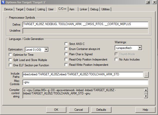
TARGET_KL05Z, NDEBUG, TOOLCHAIN_ARM, __CMSIS_RTOS, __CORTEX_M0PLUS

The include paths should contain folders (add folder with the first icon, a small rectangle):
mbed
mbed/TARGET_KL05Z
mbed/TARGET_KL05Z/TOOLCHAIN_ARM_STD

The misc Controls should contain --gnu command.

The asm tab should also have filled same Include Paths as C/C++. Copy them there.

6. step - Linker tab
Uncheck Memory Layout from Target Dialog. We need to add scatter file which is located inside mbed/TARGET_KL05/TOOLCHAIN_ARM_STD, named MKL05Z4.sct. Add it there.
This is what it should display : .\mbed\TARGET_KL05Z\TOOLCHAIN_ARM_STD\MKL05Z4.sct

Add precompiled mbed files to Misc controls which is right below Scatter file:
mbed/TARGET_KL05Z/TOOLCHAIN_ARM_STD/sys.o
mbed/TARGET_KL05Z/TOOLCHAIN_ARM_STD/retarget.o
mbed/TARGET_KL05Z/TOOLCHAIN_ARM_STD/cmsis_nvic.o
mbed/TARGET_KL05Z/TOOLCHAIN_ARM_STD/system_MKL05Z4.o
mbed/TARGET_KL05Z/TOOLCHAIN_ARM_STD/startup_MKL05Z4.o
mbed/TARGET_KL05Z/TOOLCHAIN_ARM_STD/mbed.ar

7. step - Debug tab
Now select the right radio button Use and select from drop-down menu CMSIS-DAP

8. step - Utilities
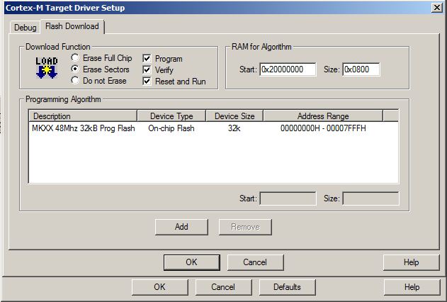
Same applies for Use Target Driver for Flash Programming - CMSIS-DAP. Click on Settings and verify everything is set according to target.


10. step - adding sources
Create new group (I name it sources) and click with your right mouse button on the group and select Add files to group .... Here's my workspace.


Now it is finally time to compile, if you followed my steps, you should get no errors ! The picture below shows window after reflashing my KL05Z, part starting with a line LOAD "C...." it's a flashing part.

We can't proceed with a bin file, due to a lack of mbed interface for our board. But CMSIS-DAP allows us to flash/debug it. Before we proceed to a debugging part, if your KL05 has not been flashed with CMSIS-DAP firmware, download it from freescale webpage - FRDM-KL05Z_QSP.zip (quick start package). There's CMSIS-DAP_OpenSDA.S19 file inside OpenSDA Applications folder. I set my board to bootloader mode and flash it with this file. Reconnect your board, and let's flash it.

Build (F7) and download your code (LOAD icon on top). This flashes KL05Z and LED should be blinking. If you want to debug it , press Ctrl+F5 (or top selection Debug -> Start/stop debuging session). Happy flashing your KL05!

If anything not clear, leave a comment.

September 10, 2013

mbed - Add library, program and create new cookbook (tip & tricks)

I have added new libraries to mbed. That was quite intuitive. I faced one problem, if you upload your own files, there are only two options - add program or library. Firstly, I added files as library, create a folder and moved all files there. I also added files as program and then moved them. What I consider as missing part there, add Folder to a project with desired name.
Adding files has its limits (I was able to import only 20 files, more were ignored).

I realized that I was adding libraries (different symbol than normal folder) at the moment when I was about to commit new library ( it asked to commit all libraries which are part of the library).
 
There is folder (folder icon) and mbed-rtos which is the library icon.

Another one, how to add new page to the cookbook. Here's an explanation, google was not my friend in the beginning:

mbed cookbook [http://mbed.org/cookbook]

Create new link (an example http://mbed.org/cookbook/my_new_link), start editing.


September 2, 2013

Hard fault - ARM cortex - get PC without any code


I would like to emphasize this small "trick" which is from the book The definitive guide to the ARM Cortex-M0.
There are many articles explaining how to write a routine to retrieve a stack frame from a hard fault. I just want to share what I use regularly. It omits details which are crucial to find out why it has crashed. However, when I get to the problematic instruction, I realize what has gone wrong and correct that error.

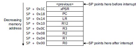
From this picture (reuse from sticky bits blog), you see that PC is stacked at Stack pointer value + 0x18. Thus what we need to to, get an SP pointer value (MSP register value usually). Add 0x18 to its value and we should see the address where hard fault was invoked. Isn't it easy?


Thanks Joseph Yui for particularly definite guide books for ARM !

August 5, 2013

mbed GCC with eclipse KL25Z (Part 1)

I have published my ongoing work, adding GCC to freedom board KL25Z. I have been using eclipse (offline compiling, debugging) with JLink (could be used with Jlink firmware for openSDA, not tested yet due to my prototype board which refuses to flash Jlink firmware). I am writing this on a laptop using windows, therefore paths included here are for windows, blame on me :-) The first part is dedicated to be able to compile an application and get a binary output.

For those who hate eclipse or don't need to debug their code, just skip steps with the eclipse. This should be your step by step routine:
install gcc toolchain, download mbed sources, build mbed library, download makefile, build an application and the last step - copy bin file to mbed file disk.

There's already cookbook for eclipse debugging on mbed eclipse for building and debugging [mbed.org]. I will refer to this guide as mbed cookbook, don't need to repeat what is trivial and usually you set an enviroment only once anyway.
We will use a different approach, clone mbed git repository, set everything in eclipse, use a makefile and set a debugger. Using this approach, you use always newest version of mbed.

1. step - Install eclipse, make and GNU toolchain
Follow Install Eclipse with C/C++ and GNU Support in the mbed cookbook. It provides information how to install eclipse and make.

2. step - Download GNU toolchain
I use GCC ARM, download it from here GCC ARM embedded [launchpad.net]

3. step - Clone mbed git repo and build mbed sources for debugging
mbed git repository is here mbed git repository [github.com]. If you don't use git, neither github, download repo as zip file. This one step is crucial for offline debugging.
As soon as you have mbed source files, there's one important link to visit Mbed Tools [mbed.org/handbook]. I'll describe what you have to do in order to get mbed library. Thus you don't need to visit mbed tools link.

Create a new file named private_settings.py in mbed/workspace_tools. Here's mine set up for ARM GCC 4.7 and also KEIL which is not our concern right now. I use debug info option as default to be able to debug mbed sources.

from os.path import join

ARM_PATH = "C:/Program Files/Keil/TAD/ARM"
ARM_BIN = join(ARM_PATH,"ARMCC","bin")
ARM_INC = join(ARM_PATH,"RV31","INC")
ARM_LIB    = join(ARM_PATH,"ARMCC","lib")
ARM_CPPLIB = join(ARM_PATH, "ARMCC","lib","cpplib")

GCC_ARM_PATH = "C:/Program Files/GNU Tools ARM Embedded/4.7 2013q1/bin"

BUILD_OPTIONS = ["debug-info"]

Time to build our own mbed library, type python build.py -m KL25Z -t GCC_ARM in the command line from workspace_tool directory. This should be an output:


At the end of the output is Build successes:   * GCC_ARM::KL25Z. There was created a directory one folder up, named build. This directory should be added to your project, that's mbed library. There's library libmbed.a and many more files which I don't need to explain here.


4. step - create new project in eclipse
File -> New -> C++ Project
Select Makefile Project -> Empty Project in Project Type, Toolchains, choose Cross GCC.


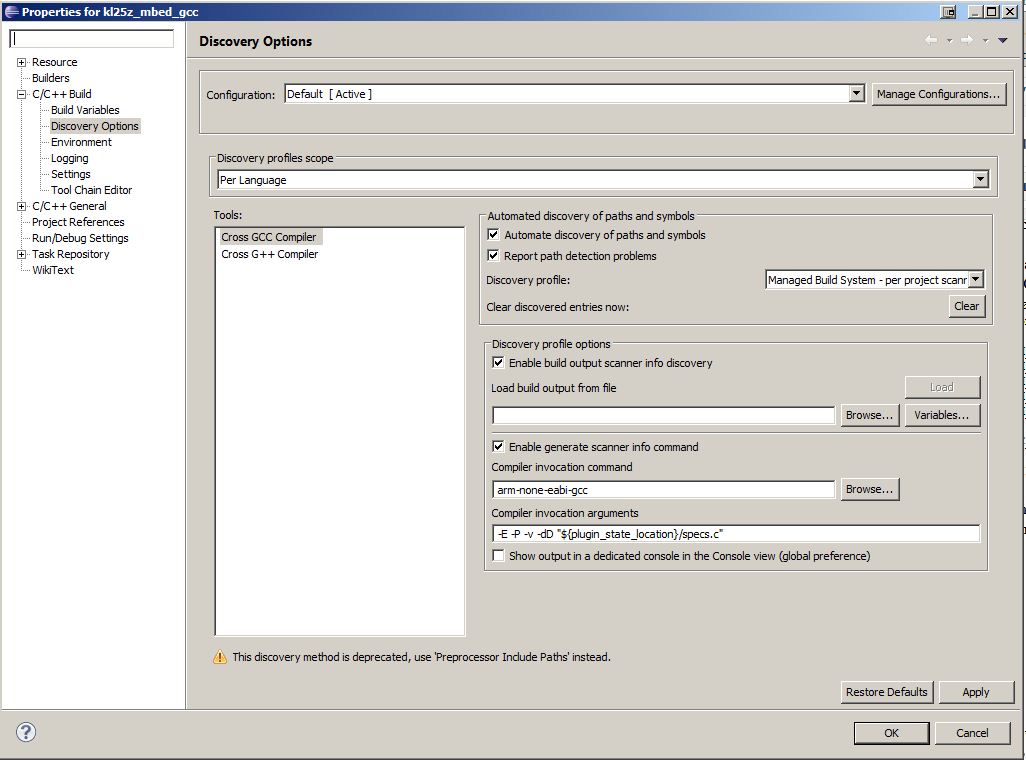
Go to the project properties as on the picture below, the compiler invocation command should be arm-none-eabi-gcc for GCC and arm-none-eabi-g++ for G++ compiler.


Click on C++ Build and uncheck Use default build command,  type there
C:\PROGRA~1\GnuWin32\bin\make.exe . Note here, that I had a problem with spaces in paths, therefore I changed PATH variable in Environment which is under C/C++ Build options. Please verify there's also folder where you installed GCC ARM (an example C:\PROGRA~1\GNU Tools ARM Embedded\4.7 2013q1\bin).


5. step - get a makefile or create a new one
This step is optional. I wrote the makefile to build an application with mbed. Download it from mbed_gcc_kl25z [https://github.com/0xc0170].

The file structure in mbed changes seldomly, therefore I include here what to check in my makefile and probably there will dwell a problem.
A variable MBED_OBJ contains object files from the mbed source. The dirs variables (INC_DIRS and SRC_DIRS) define directory structure as it is at the moment.


6. step - copy the mbed library and an application
Copy the mbed folder which is inside build directory. It's output from the step 3. I have selected to start with Hello World (KL25z examples [mbed.org/handbook]).

Here is the project tree structure.

mbed folder is folder which is copied from sources build which we did in the 3d step. main.cpp contains hello world application, makefile is my own. Files starting with . (project and cproject) are eclipse project files.


7. step - build an application
If you set everything according to this tutorial, you should be able to build an application.
Here's the output from the console:

Finished building target: out/mbed.elf

Printing size
arm-none-eabi-size --totals out/mbed.elf
   text       data        bss        dec        hex    filename
  26932        216        316      27464       6b48    out/mbed.elf
  26932        216        316      27464       6b48    (TOTALS)
arm-none-eabi-objcopy -O srec out/mbed.elf out/mbed.s19
arm-none-eabi-objcopy -O binary -v out/mbed.elf out/mbed.bin
copy from `out/mbed.elf' [elf32-littlearm] to `out/mbed.bin' [binary]
arm-none-eabi-objdump -D out/mbed.elf > out/mbed.lst
arm-none-eabi-nm out/mbed.elf > out/mbed-symbol-table.txt


The output size is huge (text section), thus we will need to tune our makefile in order to squeeze it.


One last note, I use KL25Z, to set it to any other platform should be trivial. The binary file was generated in the output folder. That one is ready to be copied to mbed.

That's compiling part. I'll continue in the next post with debugging part.